To the website
"SAROV-VOLGOGAZ"

Vibration velocity sensor DVS-I ITsFR.402248.002 Code OKP 427713

Not available

Application 

It is used for measurement of root-mean-square value (RMS) of horizontal (X channel) and vertical (Y channel) constituents of vibration velocity, vector sum module of vibration velocity RMS of X and Y channels and instantaneous value of vibration velocity via X and Y channels.

Area of application

It is used to control vibration state and structural elements of oil and gas pumping stations, steam and gas turbines, pumps, engines and other facilities.
 
While measuring the vector sum module of vibration velocity RMS of X and Y channels, the digital outputs of both channels are united. In this case only analogue outputs are used for connection, namely: current and voltage ones.
 
DVS-I adjustment and control (setting up of measurement modes and range including filters) are carried out via digital output.
 
Each DS-I channel has its internal memory (buffer) for recording measured instantaneous value of vibration velocity. The instantaneous values from the buffer including those of output voltage can be used for the purpose of diagnostics.
 
The DS-I measures the vibration velocity RMS via X and Y channels and converts the measuredvalues into a twelve-digit binary code (digital output) and dc current signals of 4 to 20 mA (current output).
 
The DS-I measures instantaneous values of vibration velocity via Х and Y channels with10 kHz sampling frequency and converts this value into output voltage of 0–5 V (voltage output).
 
The DS-I measures the vector sum module of vibration velocity RMS of X and Y channels and converts it into dc current signal of 4–20 mA (current out put via Х or Y channels).
 
The DS-I provides for data exchange (digital output) via RS-485 interface.
 
The DS-I measures the vibration velocity RMS via X and Y channels at the half, first, second and third harmonics setup via RS-485 interface of basic frequency and outputs the vibrationvelocity RMS at the harmonics via digital output – vibration velocity RMS at the first harmonic (basic frequency) via current output – an instantaneous value of vibration velocity via voltage output. The frequency is setup within the range of 50–150 Hz.
 
There is possibility to perform adjustment in operation conditions.

Technical characteristics

Measured parameters:
RMS of Х channel;
RMS of Y channel;
RMS of a vector sum module of Х and Y channels;
RMS on 0,5F; F; 2F; 3F harmonics (F – basic frequency – 50–150 Hz);
instantaneous value of signals.
 
Operating measurement range of vibration velocity RMS, mm/s From 2,5 up to Vmax*
Frequency range (LFF is switched off), max, Hz 30–4000
Cut-off frequency of digital LFF, Hz F1-500, F2-750, F3-1000, F4-1500, F5-2000
Basic relative error, % ± 7
RMS supply voltage**, V 18–36
Consumed power, W, at least 2
Useful current (supply voltage – 18 V), max, mA, at least 75
Mean time to failure, h, at least 50 000
Specified lifetime, years 12

* 25–40 mm/s.
** Power-supply circuits have galvanic isolation from output circuits and housing.

Operation conditions

Operating temperature range:
for electrodynamic transducer, °С -40 ... +180
for normalizing transducer, °С -40 ... +70
Index of protection, GOST 14254-96 IP54
  
Table
Constituent Parts*

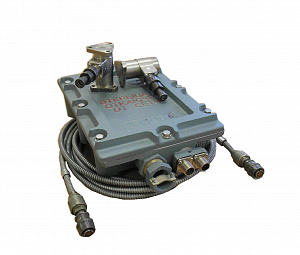
Normalizing transducer (NT)
Code Explosion-proofness Figure
NT1 1Ex[ib]mIIBT6 Fig. 1
NT2 - Fig. 2
NT3 1Ex[ib]dIIBT6 Fig. 3
Electrodynamic transducer
Code Direction of conversion Explosion-proofness
ET1 Horizontal (Х channel) 1ExibIIBT6
ET2 Vertical (Y channel)
Harness
Code Lenth, mm
L1 L1 12000
L2 24000
L3 6000
 
*Any combination of equipment is permitted. 
   
Operation details: State Register No. 32059-06. Type Approval Certificate RU.C.28.011.A No. 24526. Certificate of Conformity No. ROSS RU.GBО4.V00536. It operates at GAZPROM facilities since 2004.
 
Scope of delivery: RMS-I ITsFR.402248.002, ITsFR.402248.002PS, ITsFR.402248.002RE, CD with user program and technical documentation.