
News
All news

| Measured gaps range (displacements), max, mm | 1,2–2,5 |
| Peak-to-peak value of vibration displacement, max, μm | 125–350 |
| Rotation frequency measurement range, r/min |
nmin – nmax, where nmin = 60/ Kn r/min, nmax = 2,4·105/Кn r/min, Kn – number of gear wheel teeth, units |
| Measured passing frequency of gear wheel teeth, Hz | 1–4000 |
| Peak-to-peak value of LF vibration displacement, max, μm | 400 |
| Basic error limits: | |
|
In a displacement measurement mode, (absolute) digital output, μm |
± 40 |
| current output, μm | ± 50 |
| In a vibration displacement measurement mode |
(0,06 + 0,5/Si)·100%, where Si – measured value of vibration displacement, μm |
| In a rotation frequency measurement mode: | |
| digital output (absolute), r/min; | ± 1·10-3·nmax |
| current output (relative) |
± (0,03 +0,02 Imeasure- 4 )·100%, where Imeasure – output current value, mA |
| In a LF vibration displacement peak-to-peak measurement mode (absolute), μm | ± 20 |
| Frequency range (low frequency filter (LFF) is switched off), max, Hz | 10–1000 |
| Сut-off frequency of digital LFF, Hz | F1-500, F2-750, F3-1000 |
| Power supply voltage, V | 18–36 |
|
Consumed power, W, at least for DS with two channels |
2,3 |
| for DS with one channel | 2,0 |
| Useful current, max, (at supply voltage 18 V), mA, at least for DS with two channels | 100 |
| for DS with one channel | 75 |
| Mean time to failure, h, at least | 50 000 |
| Specified lifetime, years | 12 |
| Operation temperature range: | |
| for eddy-current transducer (ECT), оС | -40 ... +150 |
| for normalizing transducer, оС | -40 ... +70 |
| IP Code according to GOST 14254-96: | |
| for NT1 – NT6, NT9 | IP54 |
| for NT7 and NT8 | IP30 |
| for ECT (without a connector) | IP66 |
1. Eddy-current transducer according to Table 1.2.
2. Eddy-current transducer (see Section “Harness and eddy-current transducers”).
3. Harness (see Section “Harness and eddy-current transducers”).
Table 1.2
|
Код |
Канал |
Explosion protection |
Fig. No. |
|
NT1 |
Х и Y |
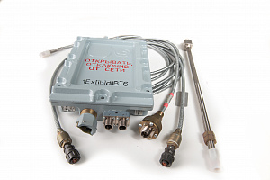
1Ex[ib]mIIBT6 |
1.1 |
|
NT2 |
One channel |
1Ex[ib]mIIBT6 |
1.2 |
|
NT3 |
Х и Y |
1Ex[ib]mIIBT6 |
1.3 |
|
NT4 |
One channel |
1Ex[ib]mIIBT6 |
1.4 |
|
NT5 |
Х и Y |
- |
1.5 |
|
NT6 |
One channel |
- |
1.6 |
|
NT7 |
One channel |
- |
1.7 |
|
NT8 |
One channel |
- |
1.7 |
|
NT9 |
One channel |
1Ex[ib]mIIBT6 |
1.4 |
Operation details: State Register No. 34132-07. Type Approval Certificate RU.C.27.011.A No. 44488. Certificate of Conformity No. ROSS RU.GBО4.VO1239. It operates at GAZPROM facilities since 2004 (“Compressor complex”, “Zavod “Kirovenergomash”, “Vega-GAZ”), Rostov NPP, Balakovo NPP.